Trends in Electrical Cables: Grid systems are one of the most important parts of life as they supply power for every need of society. None of the activity can be carried out without electricity. The electric power system is designed for efficiency, reliability, and ease of operation, and at the same time, it has to meet consumer needs at minimum cost. The grid of tomorrow must have these features and at the same time, it should meet several new requirements such as integration of various clean and distributed energy technologies, meeting the higher power-quality demands of modern digital devices, and enabling consumer participation in electricity markets.
Penetration levels of variable renewable resources, distributed generation, community energy storage, electric vehicles, and the number of active customers require substantial changes to how the grid and its various components are designed, controlled, and protected. USEIA20 (2015) reports that approximately four trillion kWh of electric energy is consumed annually in the United States, which is delivered from generators to consumers through a complex network of transmission lines, substations, distribution lines, and transformers (Fig. 1).
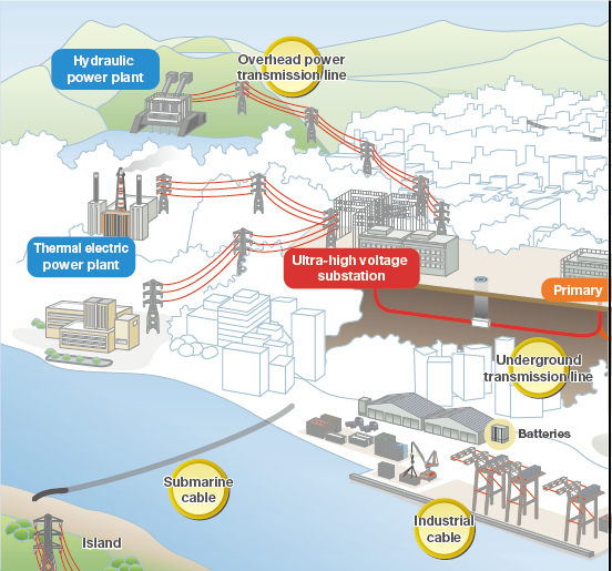
Source: Furukawa Electric Group, Japan.
Trends in Electrical Cables
The transmission and distribution (T&D) elements that make up this network are generally exposed to the natural and man-made threats from floods, cyclones, accidents, organized militant activities and threats from other unfriendly countries. Ensuring a reliable and resilient electric power system, grid components are therefore to be designed and built to withstand the impacts of lightning strikes, extreme weather conditions, electrical disturbances, accidents, equipment failures, cyber and physical attacks, and other reasons of stresses. According to Hellmuth et al. (2014), the impacts of climate change could be substantial and worsen over time, especially flooding events, which can have a significant impact on reliability. Also, Read: Trends in Solar Energy, Systems, and Products
The changing pattern of generation and load-side technologies is fundamentally changing the electric power flows and the physical phenomena, which have to be considered in future grid components. In addition, government policies related to carbon emissions reductions will have an impact on the bulk generation mix in coming years, requiring upgradation and building of transmission equipment.
About 70% transmission lines in US are 25 years or older (American Society of Civil Engineers, 2015). The age of the cables degrades their ability to withstand the physical stress and can result in higher rate of failure. Failure of cables, a key grid component, can lead to widespread outages and long recovery times resulting in high loss of revenue for utility companies and for customers who require power to do business and provide services. Consequently, appropriate maintenance of cables is of significant importance. Power outages from weather-related events and other causes are estimated to cost the United States $28–$169 billion annually (EOP, 2015). Cables and conductors was 8.0-9.0 billion dollars in 2013 and was the highest in comparison to other elements of the US transmission and distribution system (Table1).
Table 1: US Transmission and distribution market segments
| U.S. Transmission and Distribution Market Segments (2013) | Estimated Market Size ($ Billions) |
| Transformers (power and distribution) | 5.0–6.0 |
| Cables and Conductors | 8.0–9.0 |
| Towers, Insulators, and Fittings | 2.0–2.5 |
| Switchgear (e.g., breakers, “sectionalizes,” “reclosers,” fuses) | 4.0–4.5 |
| Meters (advanced metering infrastructure, phasor measurement unit, etc.) | 2.0–2.5 |
| Substations (turnkey solutions) | 4.5–5.0 |
| Power Systems (e.g., high voltage direct current, flexible alternating current transmission system, integrated solutions) | 5.5–6.0 |
| Utility Automation (e.g., asset monitoring, instrumentation, control) | 2.5–3.0 |
| Operational Platforms, Systems, and Services | 2.5–3.0 |
| Construction (substation, lines, towers) | 3.5–5.0 |
| Total | 39.5–46.5 |
USDOE (2015)
Economic growth, demographic changes, and the use of new technologies are the drivers for rising demand for electric power. More cables and conductors will be needed to increase the capacity and the interconnectivity of the grid. Installation of new cables and conductors offer preferred solution to increase transmission capacity with limited opposition from local communities. Also, Read: Plastic Trends in USA (Specific Use in Automotive Sector)
Cables are the primary carriers of electricity and are critical elements for the reliable, efficient, and cost-effective delivery of power. Cables are always insulated and are generally used in underground applications, such as for dense urban areas where real-estate costs, safety concerns, and aesthetics are important aspects. Underground cables are also used in applications where overhead lines are hard to locate, such as water crossings, and are increasingly considered advantageous for their resilience to wind and ice storms. Cables occupy less space, reduce exposure to electromagnetic frequency and do not contribute to visual irritants (Hauer, et al., 2015). Lower life-cycle costs are other points in favor of cables.
AC and DC Electrical Cables
Extruded Cross-Linked Polyethylene Insulation (XLPE)
XLPE cables were graduallyintroduced since 1960´s replacing impregnated paper cables (Europa cable, 2014). The specifications of the AC and DC cables in use are given below:
AC 1960: 20 kV / 1979: 275 kV / 1988: 500 kV
DC: 1996: ±80 kV / 2012: ±320 kV
Mass Impregnated Paper cables
Mass impregnated paper cables have been used since late 1880’s and are still used for DC applications up to ± 600 kV for transmission of power up to 2200 MW
AC transmission Vs DC transmission
AC transmission is suitable for relatively short distances and allows to realize meshed networks.
AC mass impregnated underground cables have been found to be highly reliable. However, their installation requirements are complex. Introduction of XLPE insulation enabled wide spread use of underground cable as of 1960´s. Extra High Voltage XLPE cables up to 550kV are deployed in important circuits around the world since 1990. Underground cables have gradually been deployed around the world with exponential increase in their use. Also, Read: Safety in Cement Plants and Technology
DC transmissionallows to carry high power over long distances practically without limits. These cables are still used in point-to-point connections only. Introduction of meshed / multiterminal transmission networks will depend on availability of switchgear technology. It requires conversion back into AC
Underground Cables
Underground cables are complicated and costly in comparison to overhead conductors. Per mile costs of underground cables are generally more than the per mile costs of overhead conductors but are overall economical when other factors are taken into consideration. For example, they need extra features like insulation, shielding, and thermal management. Depending on load, number of customers, various construction parameters, and the choice of technology (AC versus DC), cost per mile can vary significantly. Alternating current (AC) in underground and underwater applications over long distances have the problem of high reactive power losses. HVDC technologies are better and more economical solution. Another alternative is the use of Superconducting cables practically having no electrical resistance. Also, Read: Government Support for Indian Startup Companies
Recent development of advanced cables and conductors have been responsible for lower losses or having higher current-carrying capabilities. The new developments support more cost-effective new installations. Advanced cables and conductors are expected to reduce transmission and distribution losses and increase energy supply to end users.
XLPE AC cables
XLPE AC cables are most commonly used for various voltage ranges with varying length of years (Europacable, 2014). Details of voltage ranges and service life of different type of cables are given in Table 2.
Table 2: XLPE AC cables- Details of service life
| S.No. | Cable type | Voltage range | Service life in years |
| 1 | High voltage | 110 – 150 Kv | > 25 |
| 2 | Extra high voltage (over 1.100 km installed in Europe alone) | 220 – 275 Kv | > 20 |
| 3 | Extra high voltage (over 200 km installed in Europe alone) | 400 KV | > 15 |
The longest 40km double circuit 500 kV EHV XLPE cable is laid in tunnel in Tokyo. XLPE AC subsea cables are commonly used for submarine connections. Also, Read: Is Wastewater Coagulation an efficient water treatment method?
Core technology for “Concept of Partial Undergrounding”
Europacable (2014) suggest to complement overhead lines in sensitive areas to facilitate faster project realization. Following points are to be noted:
- ENTSO-e / Europacable joint paper recognizes availability of technology
- Decision on case-by-case basis
Examples of Best practice include:
• NL: TenneT Randstadt Project
• DK: EnergiNet policy approach
• DE: EnLAG Projects
Highlights of the technical performance of XLPE AC
Europacable (2014) gives the latest technical status of the cable as under:
- Voltages up to 550 kV
- Maximum power 1.5 GVA per circuit
- Copper conductor 2500mm2
- Joints every 700 – 1000 m (on land) directly buried into the ground or installed in underground joint bays
- 400kV cable systems carrying 5000 MVA usually comprise up to 12 cables
- Length of AC underground sections is limited up to around 20km. Beyond that, compensation may be required.
Europacable (2015) states that XLPE AC EHV underground and submarine cables are state of the art and allow for reliable electricity transmission.
Development of high voltage DC-XLPE cable systems
Application of HVDC cables have been for long-distance power transmission such as intercontinental links. In recent years, the trend is to use HVDC cables for offshore wind power generation, which is being actively being used in Europe as a renewable natural energy source. Due to space constraints, the location of wind power generation facilities is shifting from coastal areas to offshore areas. With the increasing distances, the use of HVDC power transmission is gaining popularity. Also, Read: Understanding Solid-State Batteries
DC power transmission, in earlier time, had used mass impregnated (MI) cables and oil-filled (OF) cables. However, with the rise in awareness to environmental protection, extruded insulation cables are preferred due to no fear of oil leakage accumulation. According to Murata et al. (2013), widely used cross-linked polyethylene insulation cables in AC power transmission when used in DC transmission has a number of problems in insulation i.e. prominent accumulation of space charge in cross-linked polyethylene (XLPE) insulation material. Development of high voltage DC-XLPE cables has solved this problem as they have excellent DC characteristics.
XLPE cables use cross-linked polyethylene (XLPE) as the insulation material (hereafter denoted as AC-XLPE). AC-XLPE insulation material exhibits excellent insulation performance against AC voltages, but it does not exhibit adequate performance against DC voltages due to such reasons as the accumulation of space charge. Murata et al. (2013) state that by adding nano-size filler materials in the XLPE insulator, excellent characteristic can be obtained. The XLPE insulation material for DC usage, to which nano particles have been added, (hereafter, DC-XLPE) has the following features in comparison with AC-XLPE:
- High volume resistivity
- Low space charge accumulation
- Long DC life time
- High DC breakdown strength
High Temperature Superconducting (HTS) Power Cable Technology
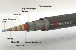
The technology Superconductors (SC) are materials that can conduct electric energy without losses below a certain critical temperature TC. These conductors are different from other standard cables like copper cables. Copper conductors are resistive and have power losses in the form of heat dissipation. Super conductors can be cooled below the critical temperature by providing cryogenic envelops (Fig.2). Thomas. et al. (2016) states that state-of-the-art cryogenic envelops allows less than 1 W of heat per meter length to enter the cryogenic system as heat influx from the environment. The critical temperature of a SC varies in a wide
SC are of two types: Low-temperature superconductors (LTS) and High-temperature superconductors (HTS). LTS can be cooled by liquid helium (T =4.2 K), whereas HTS can be cooled by liquid nitrogen (T = 77K) allowing for a simpler design of the cryogenic envelop and opening the grid applications. Super conductivity below T = 39 K in magnesium diboride (MgB2) discovered in 1981[18] provided a new promising superconductor that can be cooled by either gaseous helium or liquid nitrogen. The raw materials for this SC are available in large quantity in nature and therefore are cheaper than any other competing superconductor. Also, Read: Supercapacitors, also known as ultracapacitors or electrochemical capacitors
HTS cables are capable to deliver up to five times more electricity than the traditional conventional copper or aluminum cables and have the potential to meet the challenges of providing sufficient electricity to densely populated areas (AEP, 2015). [40] point out to the national electricity transmission and distribution losses on an average amounts to about 6% of the total electricity generated in the United States each year.40 Material advances and new designs can further help improve the new technologies.
High-Temperature Superconducting (HTS) Power Projects
HTS program was promoted by the DOE’s Office of Electricity Delivery and Energy Reliability (OE) during the period 1987-2010 and showed that the use of HTS-based applications improves the performance of electricity transmission and distribution systems (OEDER, 2015). Superconducting DC cable systems are suitable for high-power, bulk energy transfer. EPRI (2015) points out that the superconducting DC cable is considered to be more reliable and safe with substantially lower losses, fewer siting restrictions, and the ability to be terminated at distribution voltages in or near load centers (EPRI, 2015). A wide variety of applications focusing on underground cables are expanding the use of HTS materials and devices and are expected to be involved into wider applications.
Programs launched by the utility companies for the use of HTS cable have obtained significant technological achievements in Albany, New York, Columbus, Ohio, and Long Island, New York . According to OEDER (2015), the Long Island cable was the world’s first transmission voltage superconducting cable; the Albany cable was the world’s first cable to use second generation wire; and the Columbus cable operated for approximately six years in service (OEDER, 2015). Also, Read: Introduction to Sodium-Ion Batteries
HTS cable technology is becoming more popular all over the world, particularly in countries like Japan, Korea, Russia, and Europe (Synikov, 2014). A superconducting power line cable has been used in the city of Essen, Germany (the AmpaCity Project), which is expected to carry five times the power in comparison to a conventional cable with substantial cost savings (Templeton, 2014). Use of HTS cables improves the performance and reduces the cost of the superconducting wire. The technology reduces the cost of the refrigeration system and new materials with higher transition temperatures, which are added benefits.
Demonstration projects of HTS technology in the world
The use of superconducting transmission lines to transfer GW of power over long distances started about decade back (Garwin RL and MatisooJ, 1967) but now is being adopted in real grid applications [22-25] due to high performance in comparison to standard solutions. Nakicenovic et al. (1999) argues that at the moment the projects are in between innovation (demonstration stage) to niche application (field projects). A number of demonstration projects have been implemented by the utility companies worldwide or are already in operation and are fully integrated in the electric grid (Table 3) (Thomas et al, 2016). The average length of these superconducting cables is a few hundred meters and capacities are fairly low. Yet, these SCTL offer number of advantages like the ability to tailor the voltage level, especially to lower it. The AmpaCity HTS cable (MerschelF,2013; RWE, 2914) connecting two power substations in the city center of Essen holds the record with 1 km length (Spring 2014). The St. Petersburg cable will be of 2.5 km length (Sytnikov, et al., 2014). Another famous example is the LIPA project (EPRI, 2012), a 600m superconducting power cable operating in the grid at 138 kV and 2400 Ampere since 2008 and based on HTS material. LIPA realized the usefulness of the superconducting power lines as a possible solution to various needs (AMSC, 2011):
a. Right-of-way (ROW) congestion: superconducting cables provide increased power transfer capability within existing ROWs
b. Public acceptance in comparison to overhead lines
c. Potential cost savings.
Advantages of superconducting transmission lines
Superconductor transmission lines (SCTL) have the advantages similar to underground cables when compared to overhead lines:
1. Due to underground location, they have Very low visual impact on the landscape.
2. Generation of lower electromagnetic fields has low effect on the surrounding area.
3. Smaller environmental footprint than overhead lines.
4. Minimization of land use and property acquisition, leaving the value of the local real estate unchanged.
5. No affection by most of the natural weather phenomenon as such as wind, fog, snow and ice.
6. No emission of noise.
Table 3: Global superconducting cable projects that are planned to operate in the electric grid
| Project | Location | Length (m) | Capacity (MVA) | Schedule |
| LIPA | LIPA Long Island/USA | 600 | 574 (138 kV AC, 2.4 kA) | In operation since 2008 |
| AmpaCity | Essen/Germany | 1000 | 40(10KV AC, 2.3KA) | Start of operation 01/2014 |
| Amsterdam/NL | 6000 | 250 (50 kV AC) | Proposed | |
| St. Petersburg Project | St. Petersburg/Russia | 2500 | 50 (20 kV DC, 2.5 kA) | Start of operation 2015 |
| Ishikari | Ishikari/Japan | 2000 | 100(710kVDC,5kA) | Start of construction spring 2014 |
| Icheon/Korea | 100 | 154 (154 kV AC, 3.75 kA) | Operating since 11/2013 | |
| Jeju Island/Korea 1000 154 | 1000 | 154 (154 kV AC, 3.75 kA) | Operation 2015 | |
| Jeju Island/Korea | 500 | 500 (80k DC) | Operation 2014 | |
| HYDRA | Westchester county/USA | 170 | 96 (13.8 kv AC, 5KA) | Start of construction early 2014 |
| Yokohama/Japan | 250 | 200 (66 KV AC, 5KA) | Operation stopped December 2013, continuation planned with new high-performance refrigerator 2015 | |
| China | 360 | 13 (13 KV DC,10KA) | Operation since 2011 | |
| REG | Chicago/US | 5 km | To be specified | Planning since 2014 |
| Tres Amigas | New Mexico/US | 750/5000 | Postponed |
Source: Thomas, et al. (2016)
Additional Advantages of Superconducting Cables
Thomas et al. (2016) argue that SC cables offer several other advantages in comparison to the standard HVDC underground cables. The advantages of superconducting power lines when compared to the most modern underground standard HVDC cables (7320 kVXLPE HVDC) are:
- A size advantage: A 10cm width of only one SC cable is needed, compared to a 17m wide trench consisting of 24 cables for 10GW capacity for a standard HVDC ±320 KV cable installation.
- Much smaller land use potentially as low as 10% of standard HVDC cable installations depending on the capacity, area (urban or land), and regulations.
- A favorable option for long-distance and high-capacity electric energy transport if underground cables are required because standard conductor cables have high losses (46%/1000kmat 100%load for 7320 kVXLPEHVDC).
- Adjusting the nominal current to meet the desired or existing operating voltage, especially that of medium and low voltage grids thus eliminating transformers, results in less occupied space and fewer components in the grid chain that are prone to technical failures.
- Much better option for hot climates because of the vacuum-isolated cryogenic envelope that prevents heat from entering the system and therefore stabilizes the temperature of the SC conductor. The capacity of standard HVDC cables is reduced by higher soil temperatures (the resistivity of Cu and Aluminum increases with higher temperatures and so do the power losses).
- Do not heat the surrounding soil (does not alter soil humidity).
- Option for a hybrid transmission line is available, transferring not only electrical energy but also hydrogen, the fuel with the highest energy density per weight.
- Option for a hybrid transmission line is available.
- Much easier use of existing right -of – ways(ROW) to transfer GWs of power.
- Can potentially be operated in AC with much smaller losses than standard HVAC cables. The cost intensive AC-DC converters are not needed.
- The cryogenic system can store energy to lower operating temperature at times of higher renewable energy input.
Research areas for use of HVDC cables at higher voltage
Use of HVDC cables at higher voltages is underway. In 2011, cross-linked polyethylene cables for HVDC had a rating of ±350 KV (DENA, 2010). The efforts are on for ±500 kV. According to USDOE’s Advanced Research Projects Agency-Energy (ARPA-E) Green Electricity Network Integration (GENI) program is leading to improvements in this technology. Further research emphasis is required in superconducting HVDC cables, fluid-filled polypropylene paper laminate cables, and underground power delivery solutions. In addition, research on embedded sensors, new insulation materials, thermal management systems, and installation and maintenance techniques can improve the performance and lower the costs of using underground cables.
Conclusion
High Temperature Superconductors have many advantages addressing a number of public concerns. The size of the cable is a great advantage that reduce the public opposition specially in congested areas. The expansion of grid system can be expedited with use of HTS cables. Superconducting transmission lines are an innovative and promising transmission option. Their much higher efficiency and small size requirements can have direct positive impact on the environment and public support. This will help early execution and completion of the projects. The cost of the projects will be lower due to early possibilities of completion. Production of SCTL itself is cheaper. The size of the superconductors enables to minimize the outside magnetic field by choosing a proper layout for the cable system design. SCTLs can be best choice for long distances and high capacity transmission lines.
Murata et al. (2013) also conclude that DC power transmission technology is applied to the conventional long-distance and large-capacity power transmission and is also expected to find wide applications as an environment-friendly technology that enables high efficiency power transmission in conjunction with renewable energy technologies such as off-shore wind power. HVDC XLPE cable and accessories are capable of normal operation and polarity reversal operation at 90°C in actual HVDC link lines.
Europacable (2014) concludes that today, meshed AC networks secure electricity supply in Europe. In future, high voltage DC overlay networks will increasingly complement AC networks.
References
AEP. 2015. New Power Cable Technology Launched at AEP’s Bixby Station. American Electric Power. Accessed May 13, 2015: http://www.aep.com/
American Society of Civil Engineers. 2015. Failure to Act Economic Studies. Accessed March 6, 2015: http://www.asce.org/infrastructure_policy_ reports/.
AMSC. 2011. New transmission options – case study superconductor cables. Presentation.
DENA. 2010. Integration of renewable energy sources in the German power supply system from 2015–2020 with an Outlook to 2025.
EOP. 2013. Economic Benefits of Increasing Electric Grid Resilience to Weather Outages. Executive Office of the President, August 2013. Accessed March 6, 2015: http://energy.gov/sites/prod/files/2013/08/f2/Grid%20Resiliency%20Report_FINAL.pdf.
EPRI. 2012. Superconducting Power Equipment. Technology Watch. EPRI. Palo Alto, 024190;2.012.
EPRI. 2015. Program on Technology Innovation: A Superconducting DC Cable. Electric Power Research Institute. Accessed May 13, 2015: http://www. epri.com/abstracts/pages/productabstract.aspx?ProductID=000000000001020458.
Europacable. 2014. E-Highway 2050. WP3 Workshop April 25th, 2014. Brussels. 1-23.
Garwin RL and MatisooJ. 1967. Superconducting transmission lines for the transfer of large amounts of electrical power over great distances. Proc IEEE 1967. 55. 538.
Harry, Jones. 2008. Superconductors in the transmission of electricity and networks. Energy Policy. 36. 4342–4345.
Hauer, J.; Overbye, T.; Dagle, J.; Widergren, S. 2015. Advanced Transmission Technologies. Accessed March 3, 2015: http://certs.lbl.gov/ntgs/issue-6. pdf.
Hellmuth, M. et al. 2014. Assessment of Climate Change Risks to Energy Reliability in the WECC Region. ICF International for the Western Electricity Coordinating Council, December 26, 2014. Accessed March 6, 2015.
MerschelF, NoblA, StemmleM. 2013. AmpaCity—installation of advanced superconducting 10Kv system in city center replaces conventional 110Kv cables. In Proceedings of IEEE ASEMD. Beijing; 2013. 323–326.
Murata et al. 2013. Development of High Voltage DC-XLPE Cable System. SEI Technical Review. 76. 55-62.
Nakicenovic N, VictorDG, GrüblerA. 1999. Dynamics of energy technologies and global change. Energy Policy. 27. 247–280.
Norimasa,Jun Naga et al 2001. Superconductivity at 39 Kin magnesium diboride. Nature. 410. 63–64.
OEDER. 2009. Superconductivity Power Equipment. Office of Electricity Delivery and Energy Reliability, July 14, 2009. Accessed March 3, 2015: http://www. energy.gov/sites/prod/files/oeprod/DocumentsandMedia/HTS_cable_project_07.14.09.pdf.
OEDER. 2015. A National Effort to Introduce New Technology into the Power Delivery Infrastructure. Office of Electricity Delivery and Energy Reliability. Accessed May 13, 2015: http://energy.gov/sites/prod/files/oeprod/DocumentsandMedia/cable_overview2.pdf.
RWE. 2014. 〈http://www.rwe.com〉 [Online]. 〈http://www.rwe.com/web/cms/de/1301026/rwe-deutschland-ag/energiewende/intelligente-netze/ampacity/〉.
Sytnikov V, et al. 2014. HTSDC transmission line for megalopolis grid development. JPhys:ConfSer2014. 507.
Sytnikov. V. E. 2014. HTS Cable Projects in Russia. R&D Center at Federal Grid Company United Energy System, International Superconductivity Industry Summit Moscow, Russian Federation; November 12-14, 2014.
Templeton, G. 2014. World’s First Superconducting Power Line Paves the Way for Billions of Dollars in
Thomas, Heiko, et al. 2016.Superconducting transmission lines – Sustainable electrical energy transfer with higher public acceptance. Renewable and Sustainable Energy Reviews. Published by Elseveir Ltd. 55 59-72.
USEIA 20. 2015. Supply and Disposition of Electricity, 2002 through 2012. U.S. Energy Information Administration. http://www.eia.gov/electricity/annual/html/epa_01_03.html.